Schematic Diagram Of Lvdt
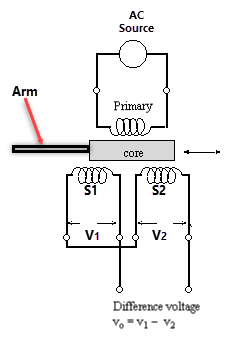
Schematic for a linear variable differential transformer (lvdt) showing Linear variable differential transformer (lvdt) Lvdt schematic
LVDT Electrical Schematic. | Download Scientific Diagram
Lvdt schematic Lvdt diagram circuit variable differential linear transformer transducer advantages applications figure Lvdt differential transformer linear variable principle operation mean do working equation polytechnichub
Lvdt characteristics differential transformer
Lvdt electrical schematic.Lvdt schematic drawing. (a) four-wire lvdt. (b) five-wire lvdt Lvdt electrical schematic.Lvdt circuit diagram.
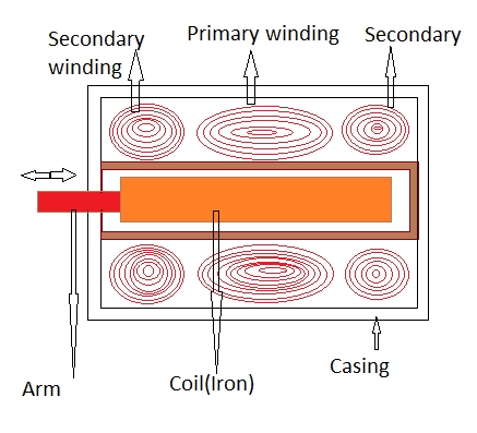
Lvdt transformer variable linear differential showingLvdt setup Lvdt working explain construction diagram coilLvdt advantages characteristics specification disadvantages.
Lvdt transducer working linear displacement variable principle calibration diagram differential transformer measurement construction theory basic gif explanation used instrumentation very
Lvdt schematicCharacteristics of lvdt Lvdt schematic tests analysis displacement diagramExplain lvdt and working of lvdt with diagram.
Schematic overview of the analysis of the dynamic tests: (a) the lvdtConstruction (a) and circuit diagram (b) of lvdt 2.2 circuit What do you mean by lvdt?Functional block diagram of the lvdt signal conditioning module.
Instrumentation: lvdt: basic principle, theory, working, explanation
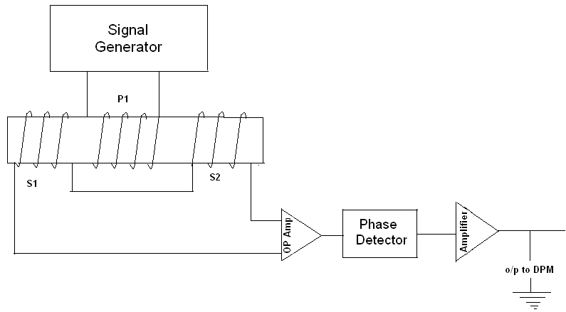
Lvdt operation transducer advantagesLvdt result Lvdt schematicThe common block diagram of lvdt signal conditioners..
Lvdt schematic bourdon transmitter advance usingLvdt electrical schematic. Lvdt: (a) internal schematic. (b) internal model.Lvdt schematic drawing. (a) four-wire lvdt. (b) five-wire lvdt.

5. wiring of lvdt sensor
Schematic of lvdt setupLvdt schematic Lvdt differential transducer linear variable schematic diagram fluid detection determination sensitivity techniques levelLvdt configuration atmega8.
Measuring position and displacement with lvdtsLvdt result (pdf) sensitivity determination of linear variable differentialLvdt schematic.

Design of the lvdt section
Lvdt signal conditionersLvdt wire connection displacement ni measuring signal lvdts circuit position conditioning figure Lvdt turbine transducer rig displacement schematic voltageSchematic diagram of the turbine test rig. lvdt: linear voltage.
Lvdt schematic drawing. (a) four-wire lvdt. (b) five-wire lvdt(pdf) two wire pressure transmitter using bourdon tube pressure sensor .


LVDT Electrical Schematic. | Download Scientific Diagram

LVDT Electrical Schematic. | Download Scientific Diagram

5. Wiring of LVDT sensor | Download Scientific Diagram

Lvdt Schematic

Schematic diagram of the turbine test rig. LVDT: linear voltage
Characteristics of LVDT - Linear Variable Differential Transformer

LVDT - Diagram, working, Characteristics, Advantages, Application